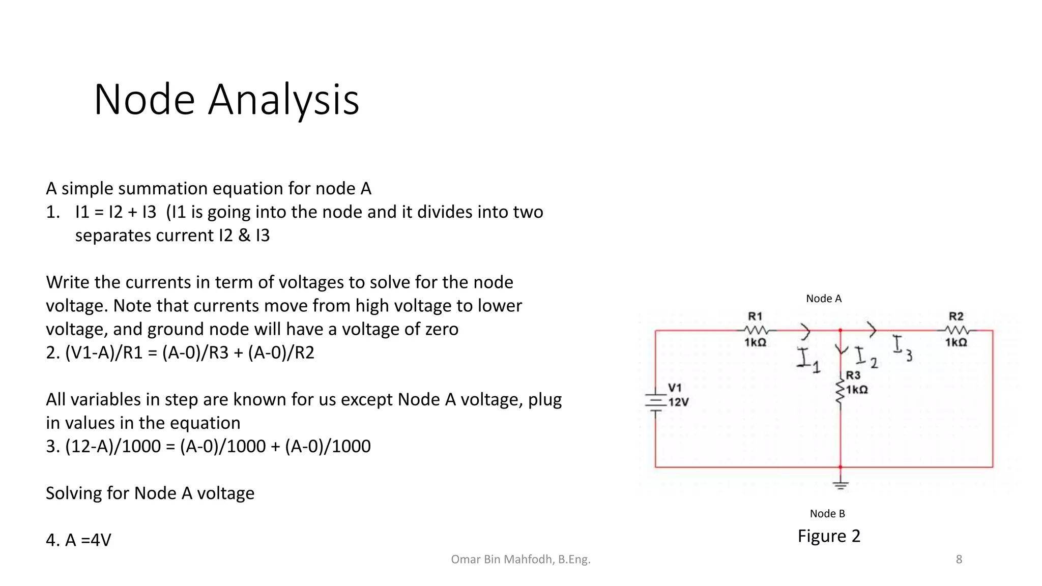
Useful Circuit Analysis Technique Circuit Diagram configuration. The art portion of analog design is designing the circuit configuration. There are many published circuit configurations for almost any circuit task, thus all circuit designers need not be artists. When the design has progressed to the point that a circuit exists, equations must be written to predict and analyze circuit performance.
ELEN-325. Introduction to Electronic Circuits: A design approach Jose Silva-Martinez - 1 - Part II. Fundamentals of Circuit Analysis. This is a design oriented engineering class; it is more relevant to understand circuit's operation and limitations that finding exact mathematical expressions or exact numerical solutions. • Circuit analysis techniques - Mesh and loop equations - Superposition, Thevenin and Norton's equivalent circuits • Integrated circuit technology - Basics process steps - PN junctions . Lecture 01 - Introduction (7/6/15) Page 01-4 R.L. Geiger, P.E. Allen and N.R. Strader, VLSI Techniques for Analog and Digital Circuits, McGraw-Hill
PDF Lecture 01 Circuit Diagram
Basic Analysis of Analog Circuits Mark Rodwell University of California, Santa Barbara rodwell@ece.ucsb.edu 805-893-3244, 805-893-3262 fax. notes, M. Rodwell, copyrighted already know analog circuit analysis well some students have not must cover device models must review some circuit analysis methods These notes: shortened version (2009

Basic Analysis of Analog Circuits Review Notes: not to be covered in lectures Mark Rodwell Doluca Family chair University of California, Santa Barbara rodwell@ece.ucsb.edu. 2 Review Notes class notes, M. Rodwell, copyrighted 2012-2024 It is expected that ECE145C/218C students be relatively familiar with analog circuit design.
Basic Analog Circuit Tutorial and Overview Circuit Diagram
CONTENTS 1 2 BJT Biasing and Thermal Stabilization Small Signal Analysis of BJT 1.1 Operating Point and DC Load Line 2 1.2 Temperature Dependence on Transistor Parameters 5 1.3 Stability Factor 6 1.4 Biasing Techniques 7 1.5 Fixed Bias Circuit 7 1.6 Collector to Base Bias 8 1.7 Voltage Divider Bias or Self Bias 10 1.8 Bias Compensation by Diode 12 1.9 Bias Compensation by Thermistor 12