
Advance Emergency Light Circuit Circuit Diagram Application of Automatic Emergency Light Circuit. An automatic Emergency Light Circuit could be used in places where the light gets on automatically as the power goes off. It could be used as an emergency lamp in homes and other places. It could be used in study rooms and workplaces in order to avoid sudden power failures. An automatic

4.The circuit should have low voltage cutoff while discharging and high voltage cutoff while charging(I think tp4056 has high voltage cutoff feature) Good backup 5.circuit should be powered with 5v mobile charger. If there is cheaper and efficient circuit than tp4056 for charging above cells in the ckt plz tell .

5 Simple Emergency Light Circuit Circuit Diagram
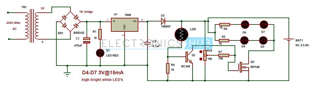
We have described the design of an Automatic emergency LED light circuit in the above discussion. We have also defined the use and working of LDR (Light-emitting resistor) in detail. We hope you have got a good knowledge of LDR working principle that will help you to understand the working of LDR in our Automatic LED emergency light circuit. As a result, we've opted to create an "Automatic Rechargeable LED emergency light circuit" in this tutorial. Automatic Emergency lighting is a simple setup circuit that may be completed quickly. The Emergency Light circuit's components are readily available and affordable. When it comes to energy saving, it's good to use that.
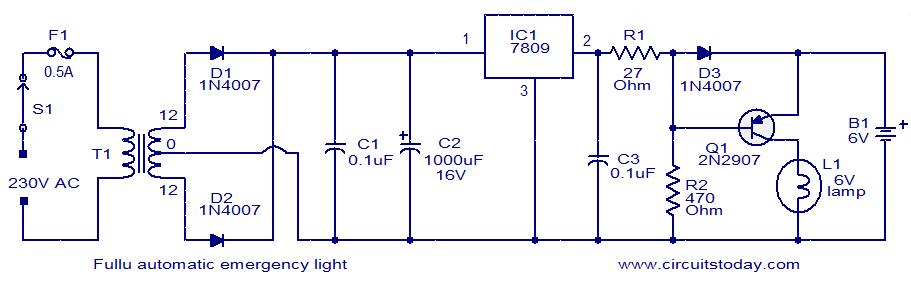
Sketch the layout of the building or area where the emergency lighting system will be installed. Identify critical locations for emergency lights and exit signs to ensure safe evacuation. 4. Circuit Design. Begin drawing a schematic diagram that illustrates the arrangement of emergency lights, batteries, switches, and the primary power source. 3) Automatic Emergency Lamp Circuit with Low Battery Cut-off. The following circuit shows how a low voltage cut off circuit can be included in the above design for preventing the battery from getting over discharged. 4) Power Supply Circuit with Emergency Light Application
How to Make an Emergency Light : 12 Steps (with Pictures ... Circuit Diagram
2) Surge Protected Automatic Emergency Lamp. This emergency light circuit incorporates surge-protection for added safety. It achieves this, by using seven diodes connected in series. These diodes are forward biased, meaning they allow current to flow through them in the intended direction. Their position is after the input capacitor in the circuit. In this circuit (12-0-12V) step down transformer is utilized as the fluorescent driver transformer that is the primary winding terminal is connected to the 20 watts fluorescent light and secondary (12-0-12V) center tapped terminals are connected with switching pulse circuit. Here VR1 variable resistor and C1 capacitor is responsible for switching pulse that is applied to the switching power
